Earth fault loop impedance measurement with MZC-320S
Loop impedance measurement with the MZC-320S can be performed using either the two-wire or four-wire method. In our step-by-step guide, you'll learn how to correctly measure loop impedance using this device.
The MZC-320S is a earth fault loop impedance tester compliant with BS EN 61557-3.

MZC-320S: Overview, Buttons, and Connections
Below, you’ll find an overview diagram with descriptions of the buttons and ports of the MZC-320S earth fault loop impedance tester.

- Power button for switching the device on/off
- Button for activating/deactivating display backlight
- Selector switch with 4 positions (AC voltage, two-wire measurement, four-wire measurement, memory)
- START button
- Arrow keys (up, down, left, right)
- ENTER button
- MENU button
- ESC button
- I1 measurement socket (2p) – two-wire measurement
- UST/T socket (UB): touch voltage measurement
- I2 socket (4p/2p) - four-/two-wire measurement
- U2 socket (4p) - four-wire measurement
- Slide safety lock for communication and measurement ports (prevents simultaneous connection)
- U1 socket (4p) - four-wire measurement
- I1 socket (4p) - four-wire measurement
- USB port
- 12V power supply connector
- Battery charge status
- Display screen
Safety warnings before measuring with the MZC-320S
- Do not touch grounded or accessible parts of the installation during measurement.
- Do not change the range selector position during measurement—this may damage the device and pose a hazard to the user.
- Using unsuitable or damaged cables poses a risk of electric shock.
- The MZC-320S is designed for operation at nominal voltages (L-N/L-L) of 110/190 V, 115/200 V, 127/220 V, 220/380 V, 230/400 V, 240/415 V, 290/500 V.
- Applying more than 550 V between any measurement terminals may damage the device.
- The CAT III 1000 V marking on accessories is equivalent to CAT IV 600 V.
Measurement conditions for fault loop impedance (MZC-320S)
Several conditions must be met before a measurement can start. The MZC-320S will block the measurement process (except for voltage measurement) if any irregularity is detected.
Warnings will be shown on the display for about 3 seconds.
| Condition | Displayed symbols and warnings | Remarks |
|---|---|---|
| The voltage applied to the device exceeds 550 V. | Message: U > 550V! and continuous tone |
Disconnect MZC-320S from the mains immediately! |
| Network frequency is outside 45–65 Hz. | Message: Error! and f < 45Hz or f > 65Hz two long beeps |
Message and tones appear after pressing START. |
| The applied voltage is too low for loop impedance measurement. | Message: Error! and U < 95Hz two long beeps |
Message and tones appear after pressing START. |
| Incorrect connection of measuring lead I1. Four-wire measurement: connected to I1 (2p). Two-wire measurement: connected to I1 (4p). |
Message: Cables connencted improperly! and Terminal I1 (2p)! or Terminal I1 (4p)! two long beeps |
Message and tones appear after pressing START. |
| Measuring lead I1 or I2. | Message: No voltage at terminals I1, I2! two long beeps |
Message and tones appear after pressing START. |
| Four-wire measurement: swapped U and I leads or connected to different phases | Message: Different voltage phases on terminals U and I! two long beeps |
Message and tones appear after pressing START. |
| Falscher Anschluss der Messleitung UB (UST/T) bei eingestellter Option zur Messung der Berührungsspannung. | Message: incorrectly connected cable! and Terminal UB! Two long beeps |
Message and tones appear after pressing START. |
| During the loop impedance measurement, the voltage dropped below Umin. | Message: Voltage failure while measuring! Two long beeps |
|
| A condition occurred during measurement that caused the test to abort. | Message: Error while measuring! Two long beeps |
|
| A fuse blew or another circuit error occurred during the loop impedance measurement. | Message: Short circuit loop faulty! Two long beeps |
|
| Thermal protection is blocking the measurement. |
Displayed symbol:
|
Tone sounds after pressing START. |
| Measurement range exceeded. | Message: OFL Two long beeps |
|
| Battery charge is low. | Displayed symbol:

|
Measurement is still possible, but additional measurement errors may occur. |
Measuring fault loop impedance: two-wire or four-wire method?
The choice between the two-wire and four-wire measurement methods depends on the expected value of the loop impedance. Based on Ohm’s law, this value can be derived from the nominal system voltage, the rated current, and the tripping characteristics of the protective device. The result gives us the maximum allowable loop impedance - the value we want to measure should fall below this limit.
Using the expected fault loop impedance, we can refer to the MZC-320S datasheet to determine whether the two-wire method is sufficient or if the more precise four-wire measurement is necessary. The following table provides the datasheet values for the measurement range and resolution.
| Measuring range | Resolution | |
|---|---|---|
| Two-wire measurement | 0.13 Ω - 199.9 Ω | 0.01 Ω |
| Four-wire measurement | 7.2 mΩ - 1999 mΩ | 0.1 Ω |
Step-by-Step: Measuring loop impedance with the MZC-320S (Two-wire method)
Follow this step-by-step guide to set up and perform a loop impedance measurement using the two-wire method.
Step 1: Configuring display parameters (Two-wire measurement)
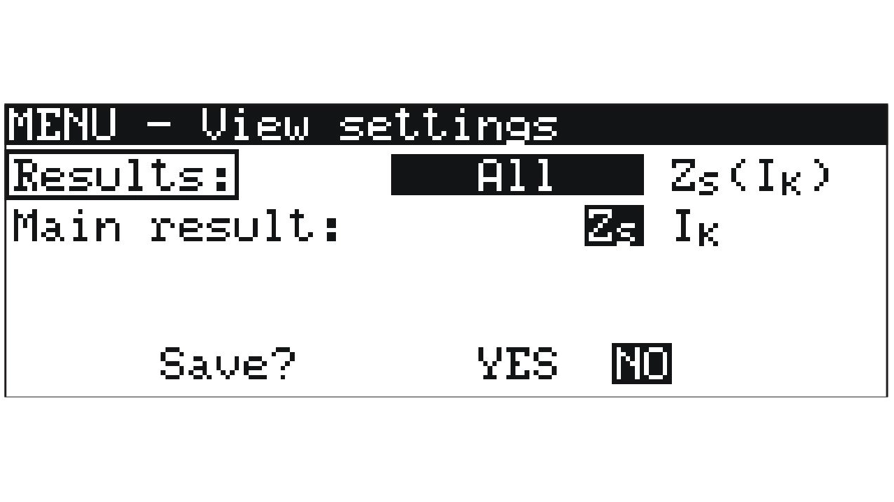
In the display settings, you can choose which parameters are shown with the measurement results. To access the selection screen:
- Press the MENU button
- Select View settings
You can choose between the following options:
- All [loop impedance, short-circuit current, resistive component (ZS), reactive component (ZS), voltage, frequency]
- ZS (IK) [loop impedance, short-circuit current]
Additionally, you can set whether ZS or IK should be the main result.
Step 2: Setting the nominal system voltage (Two-wire measurement)
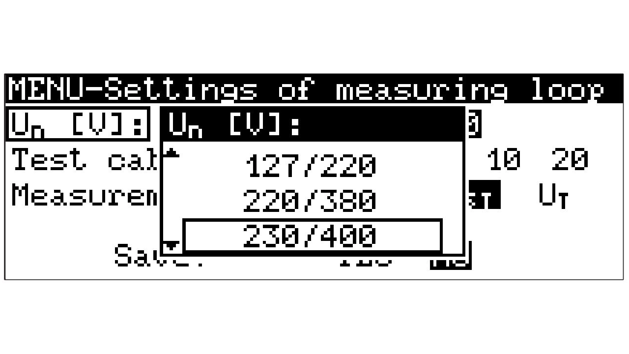
The nominal voltage is used for calculating the short-circuit current. You can set the value as follows:
- Press the MENU button
- Select Settings of measuring loop
- Under the option Un [V], choose the appropriate nominal voltage and save the setting
Step 3: Setting the length of the test lead (Two-wire measurement)
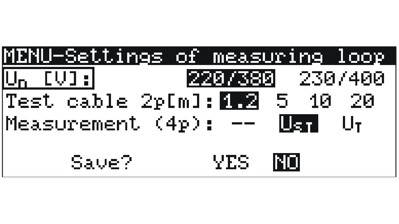
- Press the MENU button
- Select Settings of measuring loop
- Under the option Test cable 2p [m], choose the appropriate length and save the setting
Note: This setting applies to only one lead. The second lead should have the standard length of 1.2 m.
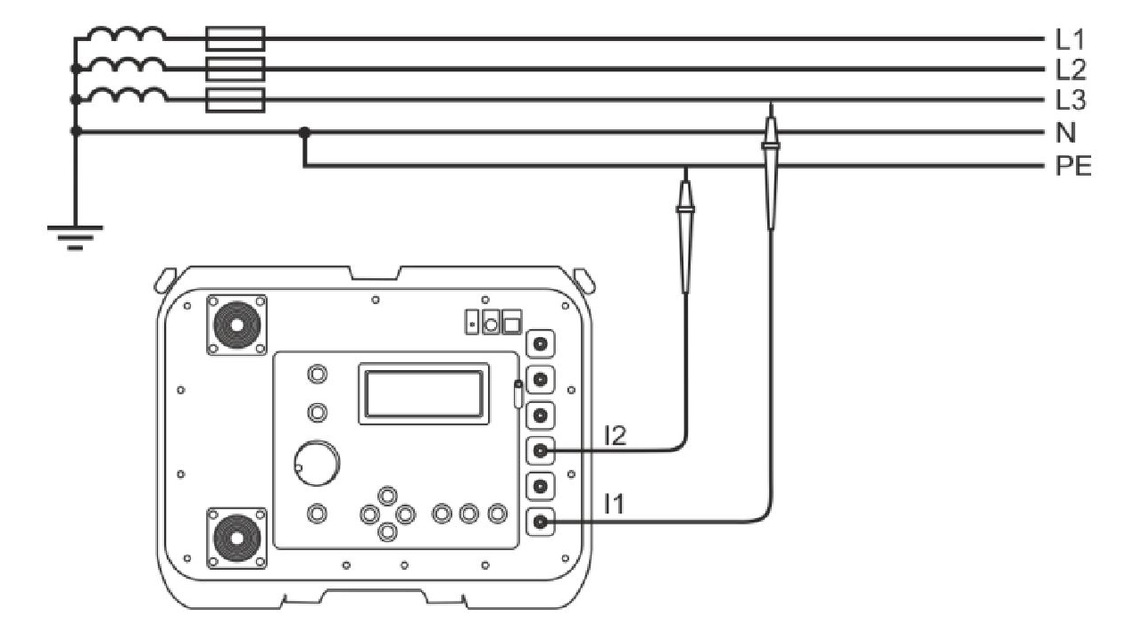
Step 4: connecting the test leads (two-wire measurement)
After configuring all parameters, turn the selector switch to the 2p position. Connect the test leads - one 1.2 m in length and the other matching the length set in the device settings - to the I1 (2p) und I 2 (yellow-marked) sockets of the loop impedance tester.
Depending on the contact options available in the electrical installation, the following accessories can be used:
- Kelvin crocodile clip
- Test probe
- Kelvin test probe
- Crocodile clip
If disconnecting voltage from the circuit is not possible, the loop impedance tester can be connected under live voltage. In this case, appropriate safety rules and personal protective equipment (PPE) must be followed.
Step 5: Performing the loop impedance measurement (Two-wire method)
In some cases, a second person may be required when using the MZC-320S. This is especially important when measuring fault loop impedance with test probes, as safe and stable contact must be ensured to avoid arcing.
Once connected to the electrical installation, measure the Z-loop by:
- Pressing the START button
Step-by-Step: Measuring loop impedance with the MZC-320S (four-wire method)
Follow this guide to set up and perform a loop impedance measurement using the four-wire method.
Step 1: Configuring display parameters (four-wire measurement)
In the display settings, you can choose which parameters will be shown in the measurement results. To access the selection menu:
- Press the MENU button
- Select View settings
You can choose between the following options:
- All [loop impedance, short-circuit current, resistive component (ZS), reactive component (ZS), voltage, frequency]
- ZS (IK) [loop impedance, short-circuit current]
Additionally, you can set whether ZS or IK should be the main result.
Step 2: Setting the nominal system voltage (Four-wire measurement)
The nominal voltage is used to calculate the short-circuit current. You can set the value as follows:
- Press the MENU button
- Select Settings of measuring loop
- Under Un [V], choose the appropriate nominal voltage and save the setting
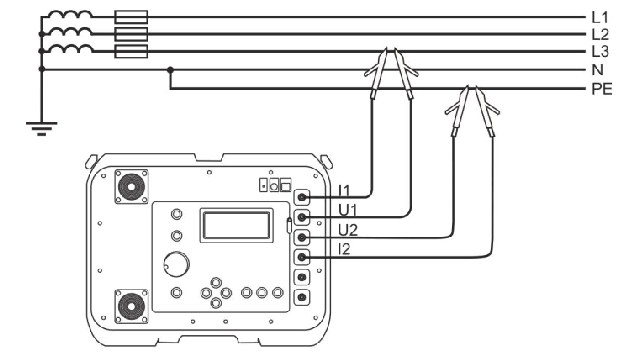
Step 3: connecting the test leads (Four-wire measurement)
After configuring all parameters, turn the selector switch to the 4p position. The two-wire test leads are connected in pairs to the I1 (4p) and U1 (4p) sockets, and to the I2 and U2 (4p) sockets (marked in red) of the loop impedance tester.
Depending on the available contact points in the electrical installation, the following connection options can be used:
- Kelvin crocodile clip
- Kelvin test probe
If voltage disconnection is not possible, the tester can be connected under live voltage for measuring the fault loop impedance. Appropriate safety regulations and personal protective equipment (PPE) must be observed.
Step 4: Performing the loop impedance measurement (four-wire measurement)
When performing a four-wire measurement with the MZC-320S, a second person should always assist if test probes are being used. Ensuring a secure connection is crucial to prevent arcing.
Once the device is connected to the electrical installation, measure the fault loop impedance by:
- Pressing the START button
Saving the loop impedance measurement
The MZC-320S loop impedance tester includes 990 memory slots, organized into 10 banks with 99 cells each.
To save a loop impedance measurement, press the ENTER button after completing the measurement. The memory location will then be displayed on the screen as follows:
A boxed bank number indicates that at least one cell in that bank is already occupied.
A boxed cell number indicates that the specific cell is already occupied.
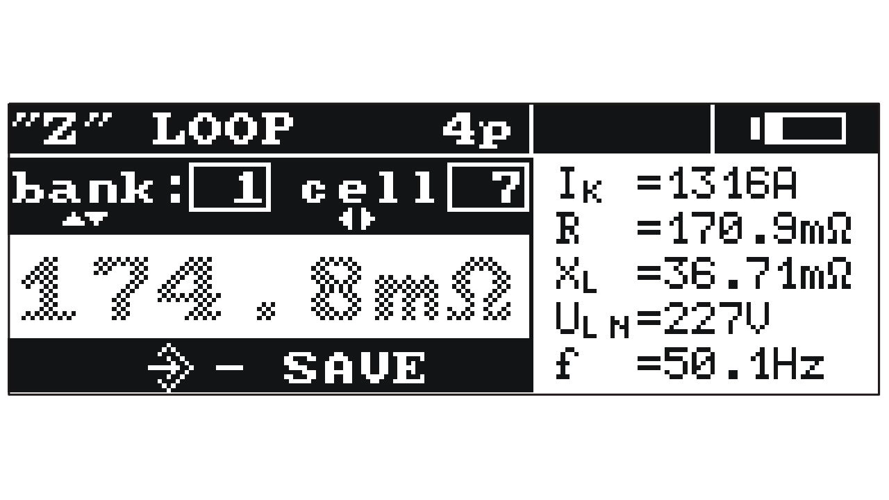
The selection of bank and cell is made using the arrow keys.
Pressing the ENTER key again saves the measurement in the selected bank and corresponding cell.
The right loop impedance tester for industrial installations
That’s why we recommend high-current fault loop impedance testers (300 A test current) from the MZC series—for reliable and accurate results even in demanding industrial settings.
")
")
")
- MZC-320S: Overview, Buttons, and Connections
- Safety warnings before measuring with the MZC-320S
- Measurement conditions for fault loop impedance (MZC-320S)
- Measuring fault loop impedance: two-wire or four-wire method?
-
Step-by-Step: Measuring loop impedance with the MZC-320S (Two-wire method)
- Step 1: Configuring display parameters (Two-wire measurement)
- Step 2: Setting the nominal system voltage (Two-wire measurement)
- Step 3: Setting the length of the test lead (Two-wire measurement)
- Step 4: connecting the test leads (two-wire measurement)
- Step 5: Performing the loop impedance measurement (Two-wire method)
- Step-by-Step: Measuring loop impedance with the MZC-320S (four-wire method)
- Saving the loop impedance measurement